Why Clamping Force Is the Most Important Spec to Get Right
The clamping force of an injection molding machine is the maximum force it can exert to keep the mold closed during the injection cycle. When plastic is injected under high pressure into the mold cavity, it pushes outward on every surface it contacts. If the clamping force is not sufficient to resist that pressure across the total projected area of the part and runner system, the mold will partially open and flash will form at the parting line.
Choosing too little tonnage is obvious when it causes defects. But choosing too much is a quieter problem. Running a part in a press that is significantly oversized for the application increases energy consumption, stresses the tie bars and mold unevenly, and ties up machine capacity that could be used for better-matched jobs. The goal is to find the right size, not the biggest available.
The Core Formula
The standard method for estimating required clamping force is based on two inputs: the projected area of the part (plus runners) and the cavity pressure factor for the material being processed.
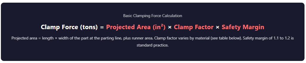
For example: a part with a projected area of 24 square inches running in polypropylene (clamp factor 3.0 tons per square inch) with a 1.2 safety margin requires a minimum of 86.4 tons. You would select a 90-ton machine as the closest appropriate size.
Clamp Factor Reference by Material Type
| Material | Typical Clamp Factor (tons/in²) | Notes |
|---|---|---|
| Polyethylene (PE) / Polypropylene (PP) | 2.5 to 3.5 | High-flow resins, lower pressure required |
| Polystyrene (PS) | 2.5 to 3.0 | Good flow, standard commodity resin |
| ABS | 3.0 to 4.0 | Mid-range viscosity |
| Polycarbonate (PC) | 4.0 to 5.0 | High viscosity, requires more pressure |
| Nylon (PA) | 3.0 to 4.5 | Varies significantly by grade and moisture |
| Glass-filled resins | 4.0 to 6.0+ | Abrasive and higher injection pressure needed |
| Thin-wall applications | Add 20–30% to base factor | Higher injection speed and pressure increase clamp demand |
Clamp factor ranges are engineering starting points for estimation. Final machine selection should account for actual gate design, runner layout, wall thickness, flow length, and process conditions. Source: ICOMold Knowledge Base, Asaclean Technical Blog, Livepoint Tooling Engineering Reference.
What Happens When You Get It Wrong
Too Little Clamping Force vs. Too Much
Under-Clamped
- Flash at parting line
- Dimensional instability
- Short shots in multi-cavity molds
- Mold damage from repeated opening
- Scrap and rework cost
Over-Clamped
- Blocked vents cause burn marks
- Excessive tie-bar stress
- Shortened mold life
- Higher energy consumption
- Machine capacity underutilized
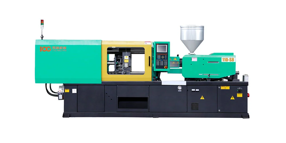
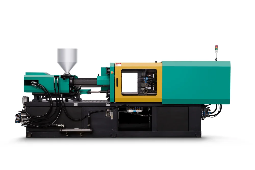
LOG IMM Machine Tonnage Range: 90 to 650 Tons
LOG IMM’s S8 and S9 Series servo injection molding machines cover the full range of commonly required tonnage in one continuous lineup, from 90 tons for small precision parts up to 650 tons for large structural components, automotive parts, and multi-cavity high-volume production.
Selecting the Right LOG IMM Tonnage for Your Application
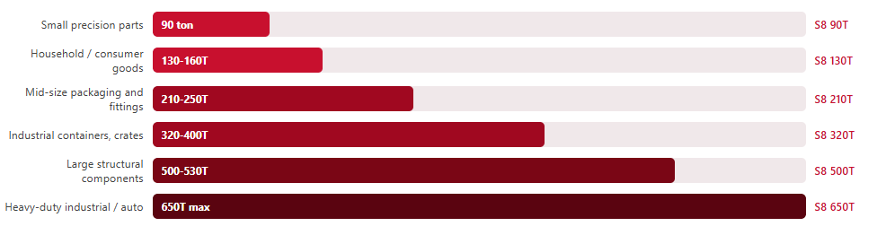
Representative size ranges. Actual machine selection depends on part geometry, material, shot size, and process requirements. Both the S8 Series and S9 Series cover this tonnage range.
Additional Factors Beyond Projected Area
The projected area calculation gives you a starting point, but machine selection also involves several other factors that can shift the required tonnage or eliminate a specific machine from consideration.
Shot size and injection capacity. The required shot weight for your part and cavities must fall within the machine’s injection capacity range. A machine with the right clamping force but insufficient injection capacity is not a match.
Tie-bar spacing and platen size. The mold must physically fit between the machine’s tie bars and on the platens. A correct tonnage calculation is meaningless if the mold base exceeds the platen dimensions of the selected machine.
Cycle time requirements. Higher cycle time demands require faster machine response. LOG IMM’s S8 and S9 servo systems are designed for fast, repeatable cycles with servo-controlled hydraulics that respond to demand rather than running continuously.
Multi-cavity molds. When calculating projected area for a multi-cavity tool, include the projected area of all cavities plus the runner system, not just a single cavity.
Not sure which LOG IMM tonnage is right for your part? Our applications team can confirm the correct machine size for your specific project.